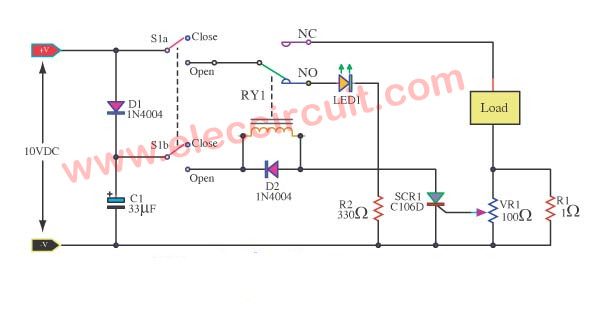
Thermal Overload Protection For Transformer Project
Simple Overload Protection Circuits Eleccircuit Com

Control Power Transformer Wiring Diagram Transformer Wiring Electrical Transformers Transformers

Transformer Less Power Supply Tutorial 52 Youtube Power Electronics Projects Engineering Projects

Rccb Protection Electronic Circuit Projects Circuit Projects Circuit

Typical Generator Transformer Protection Scheme Quantum Mechanics Generation Protection

New Wiring Diagram Of Auto Transformer Starter Diagram Diagramtemplate Diagramsample Auto Transformer Transformers Diagram
The thermal capacity used is calculated according to a mathematical model which takes into account.
Thermal overload protection for transformer project.

Relay Circuit Breaker Circuit Current Transformer Breakers

Image Result For Mike Holt Graphics Electrical Engineering Electrical Diagram Electrical Symbols

Schematic Of A Flyback Transformer Yahoo Image Search Results High Voltage Electronics Mini Projects Power Supply

Low Side Current Sense Circuit In 2020 Current Transformer Inrush Current Senses

Motorprotection Is Used To Prevent Damage To The Electrical Motor Such As Internal Faults In The Motor Electronic Engineering Electricity Electrical Wiring

Image Result For 3 Phase Wiring Diagram Australia Regulations Current Transformer Light Switch Wiring Electricity

Control Circuit With Control Power Transformer Cpt Transformers Transformer Wiring Circuit Diagram

A Complete Guide Of Current Transformer Installation And Wiring Connection With Ammeters Current Transformer Electrical Transformers Installation

How To Wire Ups Inverter With Automatic Changeover Switch Transfer Switch Electrical Diagram Electrical Panel Wiring

Difference Between Ac And Dc Current Voltage In 2020 Ac Dc Current Digital Circuit Current Generation

How To Control 3 Phase Induction Motors Elec Eng World Induction Control Electricity

Variable Voltage Power Supply From Fixed Voltage Regulator Circuit Diagram Voltage Regulator Power Supply Circuit

Pin By Shalva Khitarishvili On Elektrik Electrical Circuit Diagram Electrical Projects Electrical Diagram

Does Acme Provide Zig Zag Grounding Transformers Single Phase Transformer Transformers Machine Parts

99 Basic Electronic Circuits For You Eleccircuit Learn More Basic Electronic Circuits Pic Microcontroller Electronic Circuit Projects

Convert A Computer Power Supply To A Variable Bench Top Lab Power Supply Pictures Of Presents Variables Automatic Battery Charger

Transformer 12 Volt Dc Supply 12 0 12 Transformer 5a Youtube Electronics Projects Outdoor Toys For Kids Diy Electronics

Magnet Is Moving Back And Forth Like A Pendulum In 2020 Isolation Transformer Single Phase Transformer Electrical Transformers
1
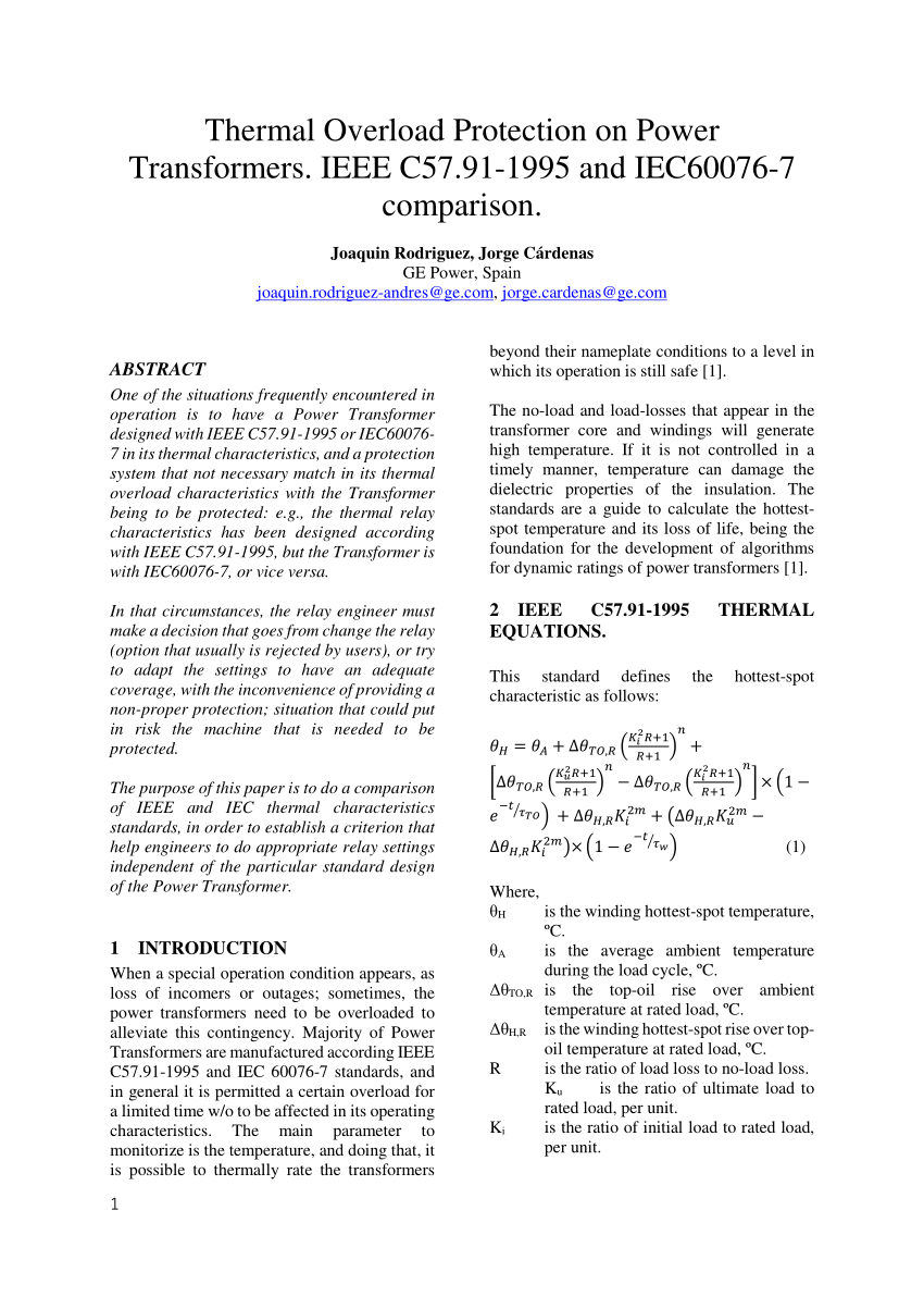
Pdf Thermal Overload Protection In Power Transformers Ieee C57 91 1995 And Iec60076 7 Comparison

Pin By Gheorghe Musat On Electronice Atx Computer Power Supplies Electrical Circuit Diagram

Transformer Connection Star Star Eep Transformers Connection Single Phase Transformer

Current Transformer Wiring Diagram Ct Installation With Ammeters For 3 Phase System Electrical On C Current Transformer Transformers Electrical Circuit Diagram

Aluminium Windings Dry Type Transformers Dry Type Transformer Transformers Electrical Engineering Projects
Source : pinterest.com
